The “Low-Background” Construction of Laboratories at the 4850ft Level Davis Campus
Introduction
The minute and rarely occurring signatures of the important physics done deep underground are always obscured by huge background contributions of all sorts, typically orders of magnitude larger. The background level is strongly correlated to the significance of the final outcome of a measurement. A host site with a low radioactivity environment is therefore a necessary starting point for most, if not all, of the modern experiments. To achieve such a low-background at an underground site, appropriate design and construction of the laboratory is essential.
Figure 1: LUX (gold) and MAJORANA (blue) laboratory sites at the 4850 Level Davis Campus at SURF. Also shown, the Yates Shaft Station (green) at lower left, to be used by science projects for equipment and personnel transport.
The goal of the Davis Campus construction team has always been to provide the lowest possible radioactivity environment for experiments that will be hosted on-site. This commitment had been integrated into the site preparation process from the early days of the US underground science program, and carried over to the realization of the 4850 Level Davis Campus laboratories shown in Figure 1.
This article will focus on naturally-occurring uranium, thorium, and potassium (U/Th/K) radioactivity backgrounds coming from: (A) the surrounding rocks; (B) the materials used for civil construction and outfitting; and (C) the airborne radon in the underground spaces and laboratories. Other backgrounds, such as those due to cosmic-ray shower muons at the underground site, will be the subject of future articles in this series. Additional shielding that will be provided in the laboratories is discussed in (D). Based on the data collected thus far, all indications are that the 4850 Level Davis Campus will be a premium underground laboratory site.
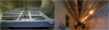
Figure 2: Laboratory outfitting taking place at the Davis Campus 4850 Level
A. Rock Radioactivity
All underground experimental devices are surrounded by an enormous mass of rock. Energetic gamma rays (~ MeV energy scale) from the natural decays of U and Th nuclei and their progeny inside the rock, and especially those originating from layers adjacent to the drifts and laboratories that survive the absorption of the rock may travel long distances to reach the active regions of the detector. Alpha particles are also emitted during the decay of the 238U-series (8α’s) and 232Th-series (4α’s) nuclei. The alphas with energy greater than the reaction thresholds of the neighboring nuclei produce neutrons that could escape from the rock. Those (α,n) neutrons that emerge may strike the detector to become a major background for many experiments (e.g. dark matter searches), or they could be captured by neighboring nuclei to produce energetic background gamma rays. While some of these gamma and neutron backgrounds could be suppressed by experimental control such as shielding, an ideal host site should have low radioactivity rocks to begin with.
It is well known that the amount of U/Th/K in rock species is very site-specific and varies significantly even within the same site. It is prudent to explore and pre-select regions of the mine that are most suitable for constructing low-background laboratories. The geology and rock formation of the Homestake site have been well-studied and documented in the past. Figure 3 illustrates, not to scale, the several major rock formation types at the Homestake Mine (a vertical cross section close to the Davis Cavern [Ref. 4]).
A rock radioactivity assay program [Ref. 5] was established by W. Roggenthen (South Dakota School of Mines & Technology) and A.R. Smith (Low Background Facility, Lawrence Berkeley National Laboratory, Figure 4, [Ref. 6]) early on to analyze the radioactivity of old rock samples from the Homestake Mine Core Library and other collections, as well as newer samples extracted from accessible levels of the mine since 2007 (Figure 4).
Figure 3: Typical vertical rock formation cross-section at the Homestake Mine: (a) projected Flagrock formation; (b) projected Northwestern formation; (c) Ellison formation; (d) Homestake formation; (e) Poorman formation; and (f) projected Yates member of Poorman formation. Small white patches (g) are Rhyolite intrusions (based on a drawing by K. Hart, SURF).
Table I shows some of the assay results, obtained by direct gamma counting, for rock samples from the mine, including those collected close to the 4850 Level. It was found that indeed the U/Th/K radioactivity for the underground bedrocks at Homestake is in general very low; some samples are in the sub-ppm levels. However, samples from Rhyolite intrusions, a very small fraction of the total (Figure 3), show a relatively high content of U, Th, and K. Regions of potential Rhyolite intrusions have been identified and documented. Were the exact location of these sparse Rhyolite exposures known, one could introduce engineering controls and other means (such as thicknesses of construction materials and shielding) to reduce their background impact.
|
|
Uranium (ppm) Ave. [Range] |
Thorium (ppm) Ave. [Range] |
Potassium (%) Ave. [Range] |
|
UG Country Rock |
0.22 [0.06-0.77] |
0.33 [0.24-1.59] |
0.96 [0.10-1.94] |
|
Shotcrete |
1.89 [1.74-2.23] |
2.85 [2.00-3.46] |
0.88 [0.41-1.27] |
|
Concrete Blocks |
2.16 [2.14-2.18] |
3.20 [3.08-3.32] |
1.23 [1.27-1.19] |
|
Rhyolite Dike |
8.75 [8.00-10.90] |
10.86 [8.60-12.20] |
4.17 [1.69-6.86] |
B. Construction Material Radioactivity – Shotcrete and Concrete
Table 1 lists the U/Th/K average contents of samples of the three accepted shotcrete types. Post-built shotcrete samples were also assayed for quality assurance purposes. During the later stage of laboratory outfitting, many partition walls and interior structures will be needed, many being of concrete wall blocks (Figure 4). Their measured radioactivity contents are also shown in Table 1. Note that the radioactivity levels of the construction materials for the Davis Campus are worse than those of the bedrock. An accurate mapping of the location and quantity of the shotcrete material applied has been documented by the construction team and will be made available to the scientific community in future.
The project team [Ref. 7] has done a detailed pre-construction laser scanning for the geometrical profiles (Figure 5) of the newly-excavated laboratory spaces. By repeating the same laser-scanning procedure after the shotcrete work has been completed, one can infer the thickness profile of the layer from the differences.
Figure 5: Geometrical profile of Davis Campus at the 4850 Level obtained by laser scanning (courtesy of the Engineering Department, SURF).
The thickness distributions of the as-built shotcrete layer on the inner surfaces of the LUX and MAJORANA laboratories are shown in Figures 6 and 7. The 3D rendition on the left depicts the actual cavity geometries after excavation, and the histogram to the right summarizes the accumulated thickness distribution sampling over the respective boundaries of the laboratory. The typical thickness is ~5 inches for the LUX cavity and ~4 inches for the MAJORANA laboratory. In terms of radioactivity, there are two main consequences of an added shotcrete layer; it could (a) attenuate some of the gammas from the bare rock, and (b) contribute additional radioactivity to the experimental halls.
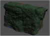
Figure 6: Thickness distributions for shotcrete layers in the LUX Davis Cavern deduced by laser-scanning techniques. Peak of distribution is at ~5 inches (courtesy of SURF).
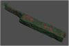
Figure 7: Thickness distributions for the shotcrete layers in the Transition Area (Mechanical Room and MAJORANA DEMONSTRATOR) deduced by laser-scanning techniques. Peak of distributions is at ~4 inches (courtesy of SURF).
Figure 8: Geant4 simulation for rock gamma attention factors in 5-inch thick layers of shotcrete/concrete. Gammas could traverse more than nominal thickness at off-normal impinging angles.
A Monte Carlo simulation with the latest version of Geant4 has been performed [Ref. 8] by approximating the Davis cavity with a similar-sized rectangular-shaped volume, with the inside walls lined uniformly with a 5-inch-thick layer of shotcrete, with known U/Th content for the assay data. The simulation indicates that on average such a shotcrete layer could attenuate 2.6 MeV gamma rock gammas by a factor of ~5 (Figure 8). By comparing numbers in Table 1, one can see that the actual effect will depend on the rock types behind the shotcrete. This information is available for experimenters performing their detailed background studies.
C. Shielding Provision - The Multi-purpose Water Shielding Tank (71,600 gallons) and Steel Floor Plates at the expanded Davis Cavern
An important mitigation technique for reducing the impact of environmental radioactivity is to implement additional engineering (passive or active) shielding controls.
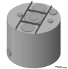
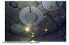
Figure 9: Left: Isometric exterior view of [8-m diam. x 6-m height] general-purpose water shielding tank at the 4850 Level Davis Laboratory. Right: Looking from the inside up of the tank.
To prepare for the present and future experiments that could benefit from a large volume water shield (e.g. dark matter search experiments), a large size (8-m diameter x 6-m height) multi-purpose water tank has been included in the onset as part of the expanded Davis Cavern outfitting program (Figure 9). This 71,600-gallon capacity water tank will host the LUX experiment initially, but its size is large enough to be used by future experiments as well (e.g. a generation-2 dark-matter search experiment). The construction of the tank and water-handling infrastructure is well under way. The efficiency of this water tank in shielding environmental rock gammas and external neutrons has been thoroughly studied by the LUX collaboration [Ref. 2].
Another significant structural addition to the Davis Cavern is a massive octagon-shaped steel plate lying at the central portion of the room (Figure 10), to provide additional shielding for external radioactivity from the floor. The structure is made up of steel plates--each 2 inches thick (up to 12 inches in the middle), lying on top of each other. Another large collection of steel sheets, gathered from the original chlorine tank of the Davis solar neutrino experiment after it was dismantled, is stored underground for possible future experimental applications.
Figure 10: Top (upper left) and elevation views of octagon-shaped thick steel floor-shield installed as part of the laboratory outfitting program.
D. Recent Radon Levels
Airborne radon daughters from the U and Th chain could plate on surfaces of detector components or dissolved in the liquid media during detector construction and operation to contribute to long-term experimental backgrounds. A well-known case is the 210Pb daughter isotope from 222Ra, which has a long enough half-life to be present for the duration of a typical experiment. OSHA regulations on permissible radon levels are in place for the working environment as well.
SDSTA staff and collaborators continue to monitor the underground radon level at different depths and drift locations. Specifically, radon data has been accumulated continuously at the 1250 Level and 4850 Level for more than 900 days since 2009 (Figure 11). Due to the work-in-progress status of the site ventilation system, many of the measurements may not be representative of what the final values could be, but the latest trend since 2011 at the Yates Shaft 4850 Level has been quite promising (Figure 12). In particular, an airborne radon level of ~120Bq/m3 has been observed over a period of several months. The final achievable radon level will not be known until the laboratories are in full operation.
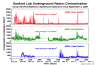
Figure 11: Airborne radon levels from radon monitors installed at 1250 and 4850 Levels near Ross and Yates Shafts. Yates Shaft is very close to the Davis Campus.
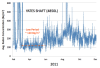
Figure 12: Radon levels at Yates Shaft area (4850 Level). A relatively low level period(~ 120Bq/m3) was observed during a three-month period in 2011.
Summary
It is an exciting time for the underground science community as laboratories at the 4850 Level Davis Campus are close to being completed. The project team’s commitment to create a low-background laboratory for future scientific experiments has made a significant difference. Once beneficial occupancy is allowed, more detailed in-situ background characterization of the Davis Campus Laboratories will be performed. The detailed background radioactivity information provided by SURF will help to refine analysis results and aid in planning for future generations of experimental devices at Homestake.
(Contributors to this article: Y.D. Chan, J.A. Detwiler, K. Hart, R. Labahn, W. Roggenthen , A.R. Smith, D. Vardiman, J. Willhite, C. Zhang.)
References:
[1] Davis, R. 1964: Phys. Rev. Lett. 12, 303, Davis, R. et al. 1968: Phys. Rev. Lett. 20, 1205, Davis, R. et al. 1971. Bull.Am.Phys.Soc. II 16, 631.
[2] LUX, http://lux.sanfordlab.org/main/
[3] MAJORANA DEMONSTRATOR Project, http://www.npl.washington.edu/majorana/
[4] Kathy Hart, SURF (SURF , Private Communication)
[5] W. Roggenthen and A.R. Smith, White Paper: U, Th, K contents of materials associated with the Homestake DUSEL site, Lead, South Dakota. (Private Communication); A.R. Smith, Homestake Samples: Results of Radiometric Analyses at LBNL (Private Communication);
[6] LBF is an open facility operated by the Nuclear Science Division at LBNL, supporting the science community since 1962. See:
http://lbf.lbl.gov/preview/index.html and http://cosmology.berkeley.edu/DUSEL/Town_meeting_DC07/working_groups/b1/talks/Oroville.pdf
[7] SURF shotcrete laser scan profiles (Contact: SURF Engineering Department, Private Communication)
[8] J.A. Detwiler (Geant4.9.5, LBNL, Private Communication)